Industrial Automation SCADA System
Tamimi August 07, 2014 [Professional] #Project Management #Engineering #IIoT #SCADA #PLC #RTU #Wireless Communication #Rockwell #Allen Bradley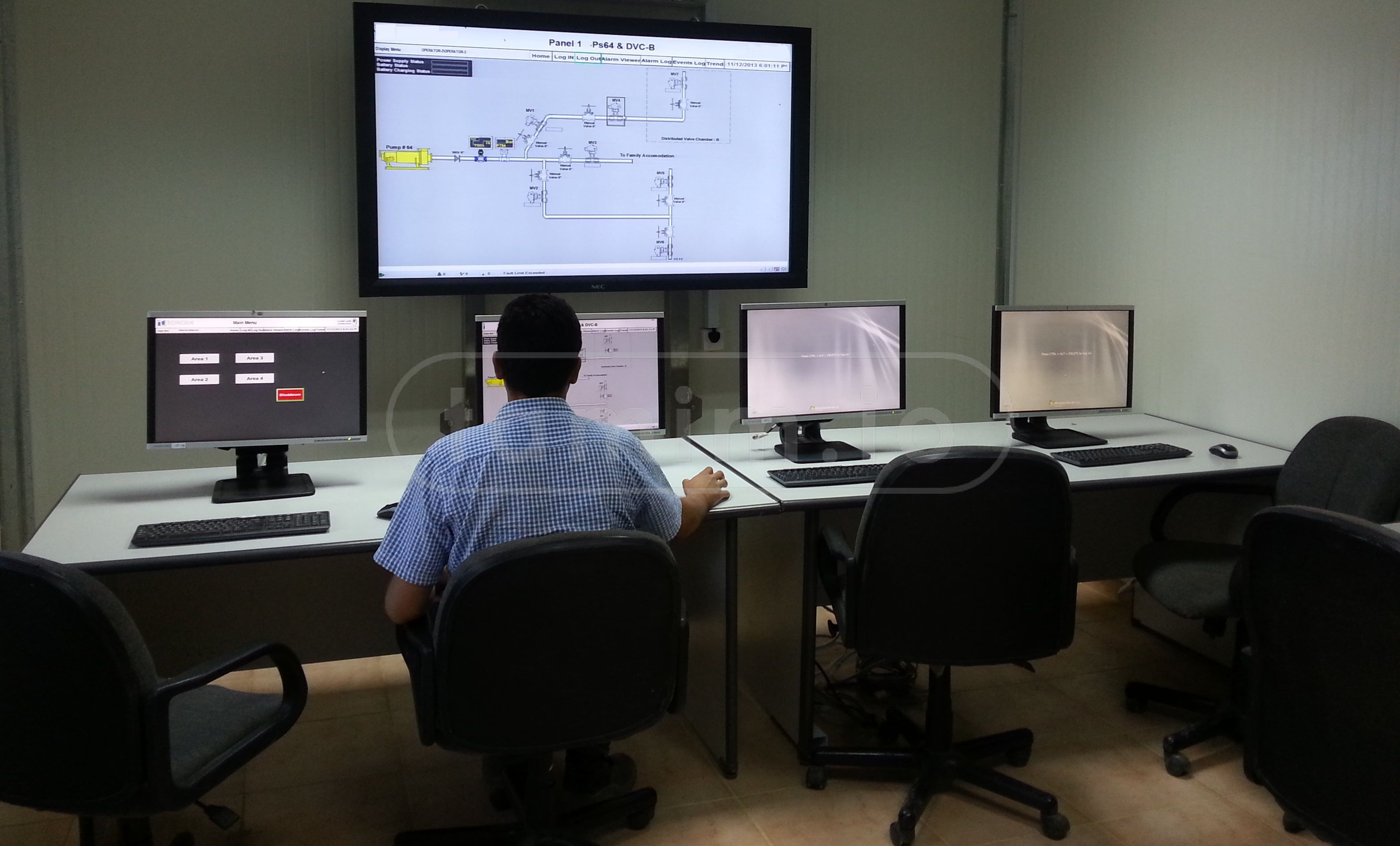
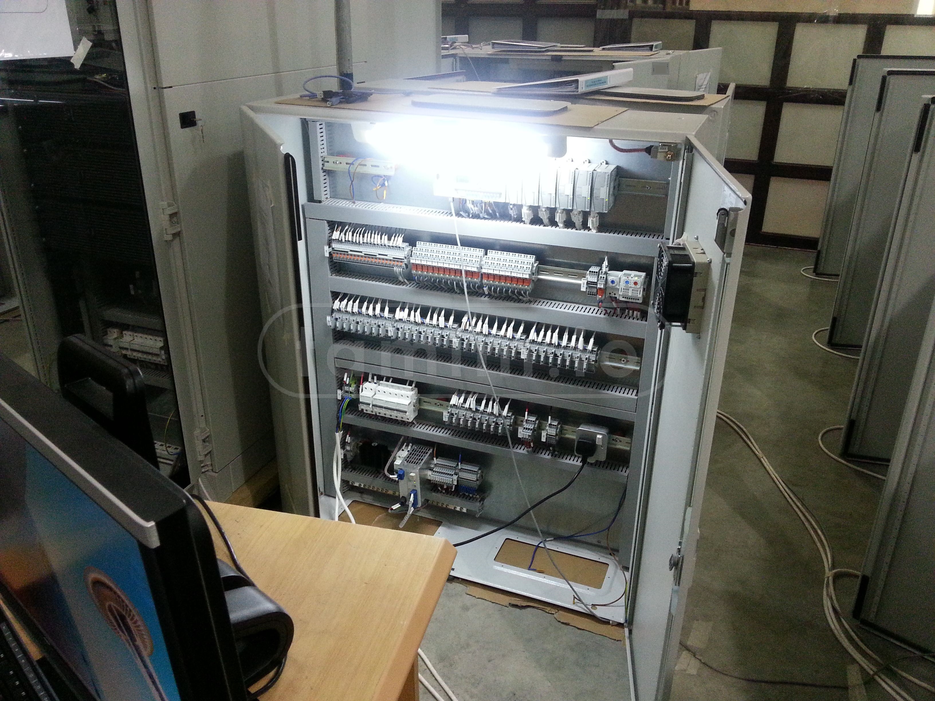
Img1: The MCC for this project
| Project | Industrial Automation SCADA System |
|---|---|
| Company | AWP |
| Clients | redacted |
| Budget | US$2.4 million |
| Duration | 24 months |
| Status | Successfully Delivered |
Introduction
This project was a turnkey solution that transformed a large-scale operation that relied on manual labor and outdated methods into a fully automated and monitored system that could be controlled and accessed from anywhere. The project leveraged the power of SCADA (Supervisory Control and Data Acquisition) to revolutionize the old operation methods. The project not only installed the SCADA system, but also overhauled the entire infrastructure, including the civil and construction work, the wireless communication, the field devices, the solar power, and the data center room. The project was a complex and challenging one, but also a rewarding and learning experience for me and my team. In this report, I will describe the requirements, scope, design, implementation, and challenges of this project, as well as the outcomes and future prospects.
Requirements
The project had many requirements, such as:
- Designing, developing, procuring, and configuring a turnkey SCADA system that replaced the manual operations.
- Having full control over the system components, either through the operator in the MCC or autonomously.
- Implementing an alarm system with different degrees of alarms, both active and predictive alarms based on the history of the collected data.
- Collecting data and storing it in a historian database, with a retention period of 20 years.
- Providing extensive reporting and data post-processing, built into the system.
- Establishing wireless communication that covered the project area, with future scalability.
- Enabling remote monitoring system, accessible through the internal company network.
- Building and preparing a small data center room to house the MCC (Main Control Center).
- Performing infrastructure work, including cabling, wireless communication, antenna placement, directions, etc.
- Powering the off-grid location by solar systems, which became a separate project later, more on Off Grid IIoT Solar System
Scope
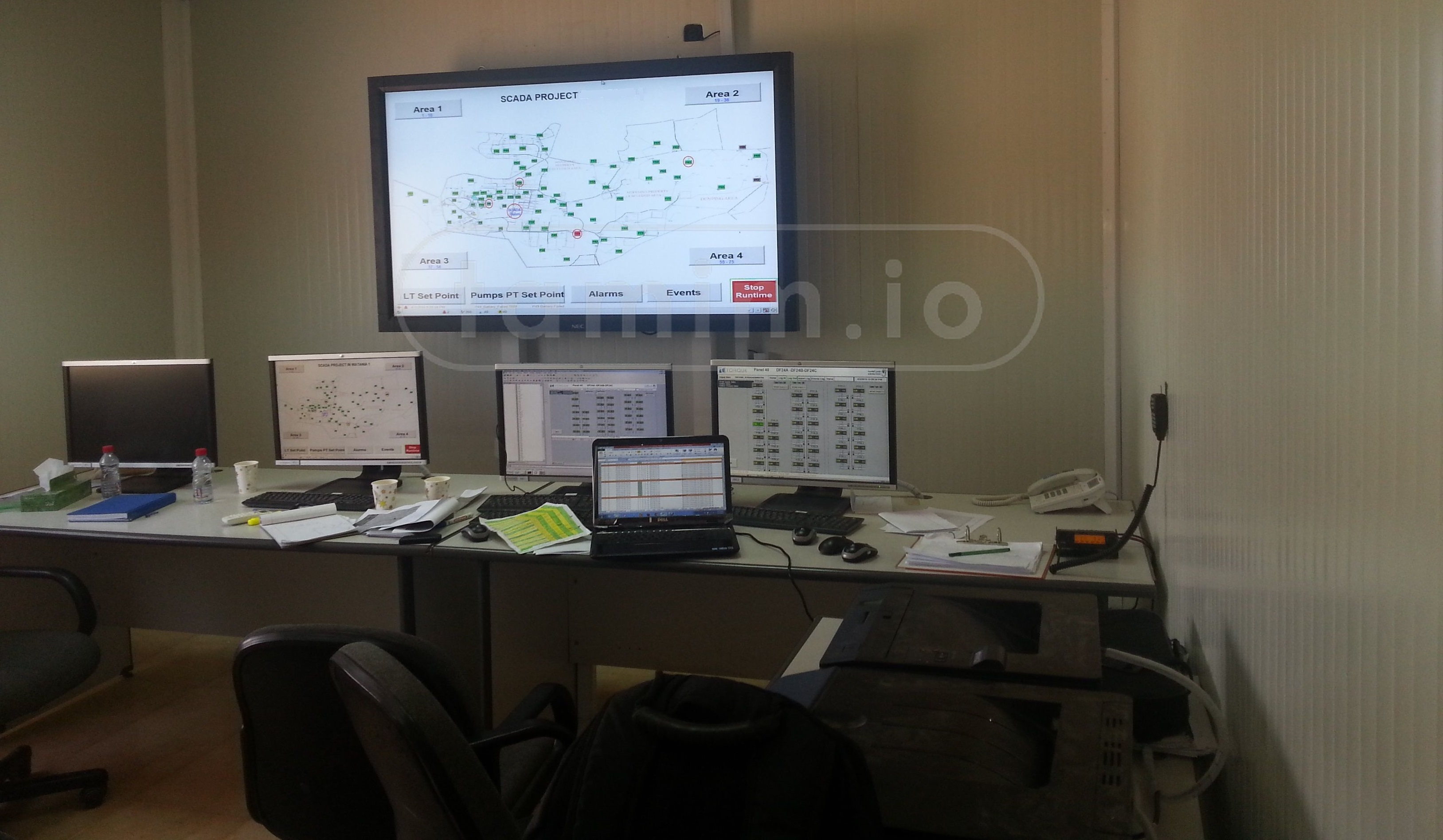
Img2: The interface of the project
The scope of the project was large and required a lot of planning to execute. The project encompassed several fields in one, from IT to OT, automation and engineering, radio and wireless communications, all the way to pure electric and mechanical work. The design and procurement stage was challenging, but not as challenging as the installation and testing one. I had a team of 60 individuals reporting to me, including engineers, technicians, and technologists. The major components of the scope were as follows:
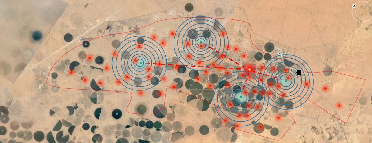
Project Area
The project area was vast and remote, with dimensions of around 15km in length and 7km in width, mostly consisting of off-road and non-serviceable terrain. The goal of this project was to automate the operation, so the operators did not waste time and resources just to flip a switch, and to enable continuous monitoring.
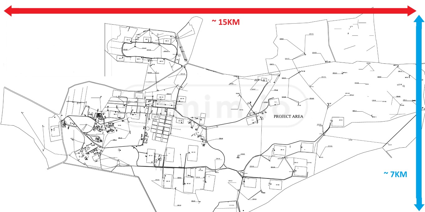
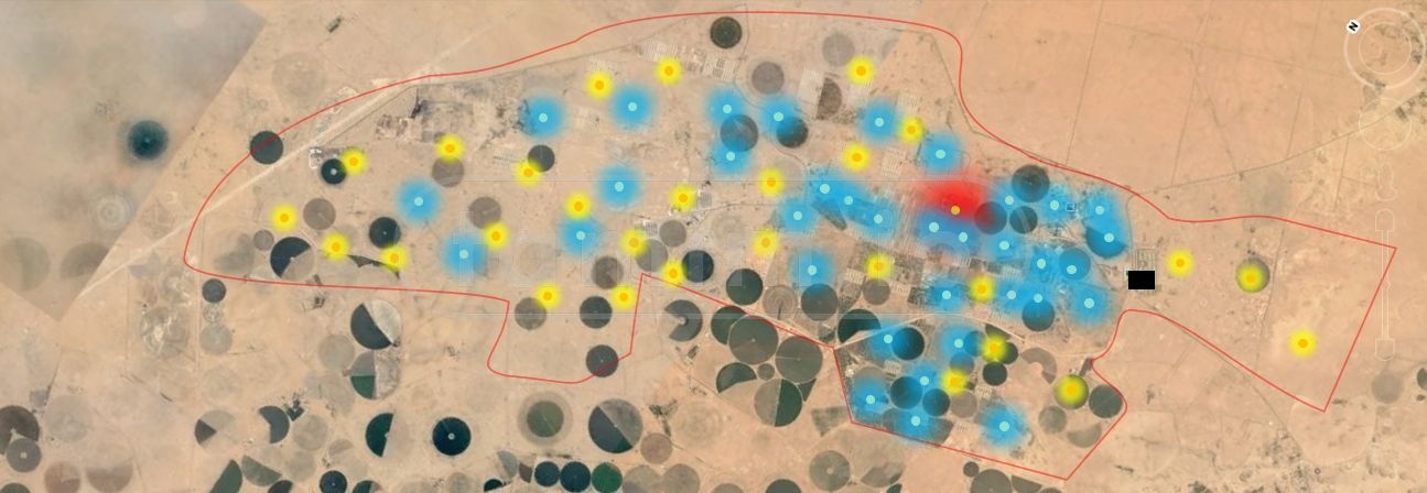
Img3: The project area
Due to the size of the area, it was mainly divided into four zones, which served as the boundaries for the wireless communication, cabling, network stack, and even within the SCADA interface.
Field RTUs/IoT
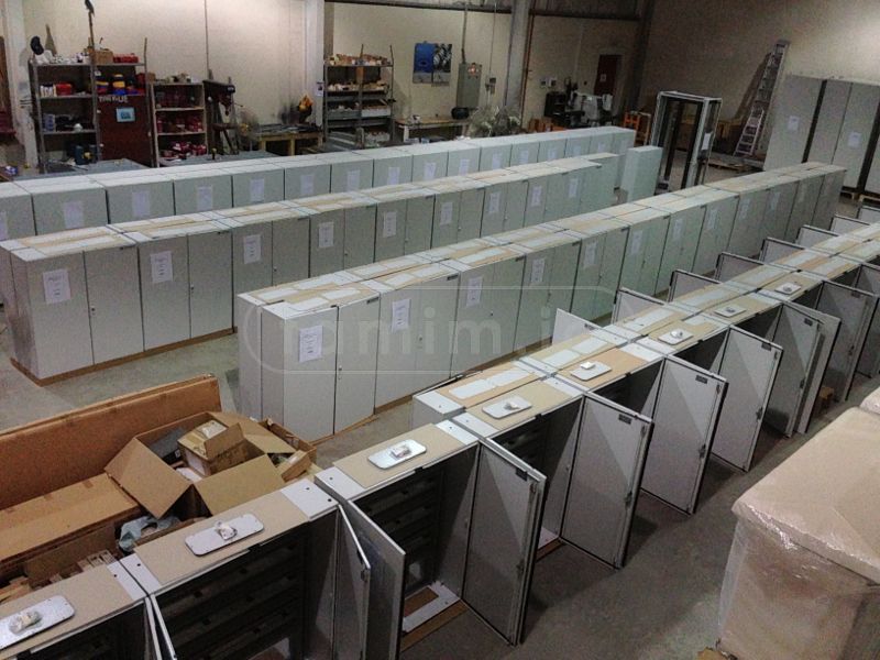
Img4/5: The RTUs at the Factory Acceptance Test - FAT
The project consisted of a total of 75 RTUs - active ones, excluding the spare RTUs - installed in the field. Each RTU served different purposes and controlled different field devices, each one having the following:
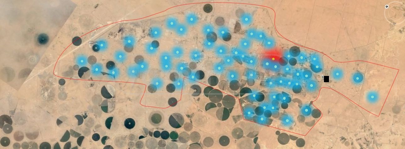
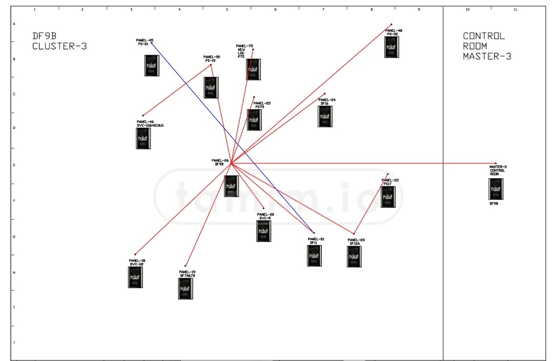
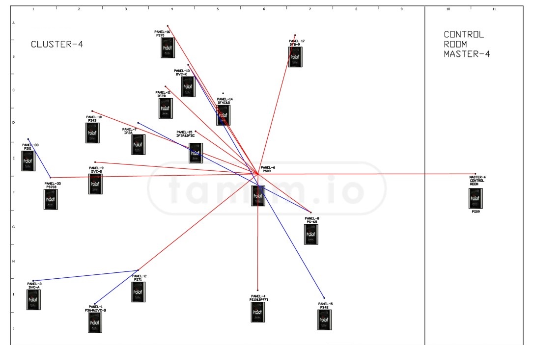
Img6: The RTUs locations in the project area, red dot is the MCC
- The PLC unit, Micrologix 1400
- The required IOs, such as analogue and digital IOs expansion cards.
- The wireless communication unit, Prosoft Industrial Hotspot.
- Weatherproof IP65 panels, with the necessary peripherals like relays, DIN rails, circuit breakers, etc.
- Solar panels in some locations.
- Connected field sensors, instruments, and devices.
- Other mechanical components like antenna posts, etc.
PLC Micrologix 1400 description from the manufacturer for a technical background:
The Allen-Bradley® MicroLogix™ 1400 from Rockwell Automation complements the existing MicroLogix family of small programmable logic controllers. MicroLogix 1400 combines the features you demand from MicroLogix 1100, such as EtherNet/IP, online editing, and a built-in LCD, plus provides you with enhanced features, such as: higher I/O count, faster High Speed Counter/PTO and enhanced network capabilities
Three embedded communication ports provide you with excellent communications capabilities. MicroLogix 1400 off ers an isolated RS232C/ RS485 combination port; a non-isolated RS232C port; and an RJ-45 port for 10/100 Mbps EtherNet/IP peer-to-peer messaging, DNP3 over IP and Modbus TCP/IP protocol
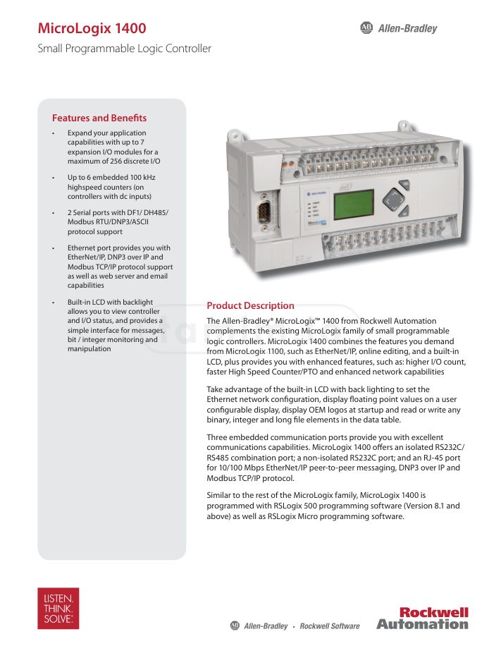
Img7: MicroLogix™ 1400, the PLC used in the RTUs
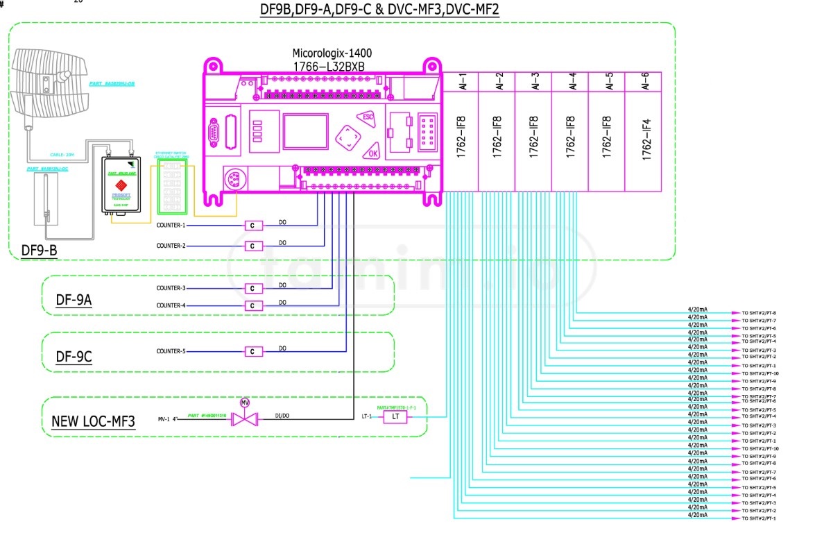
Img8: One of the RTU diagrams
The PLCs were programmed with ladder logic 1, a very simple language to control the logic. However, due to the size of the project, the number of RTUs, and the fact that each one of these RTUs was different (not identical), it was daunting to go through all of it, test it, and commission each single functionality.
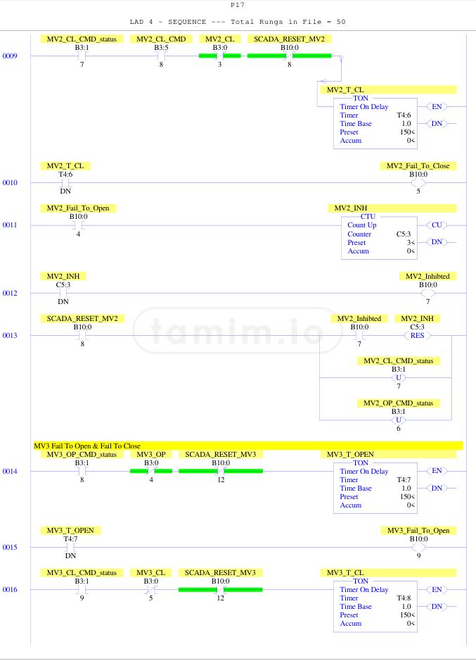
Img9: A sample of the ladder Language, this is part of one of the RTU's PLC
Off-grid RTUs
Some RTUs were located in areas that had no grid connection nearby. The feasibility study I did in these locations showed that using solar panels was cheaper in the long run than being grid-connected. The costs of the construction work, electrical and cable work, and the price of the electricity were considered for the grid-connected ones, while the battery and maintenance costs for the solar ones.
Img10: The location of the RTUs that are off-grid and powered by the solar panels
This became a separate follow-up project, so I will have all the details in here Off Grid IIoT Solar System
MCC (Main Control Center)
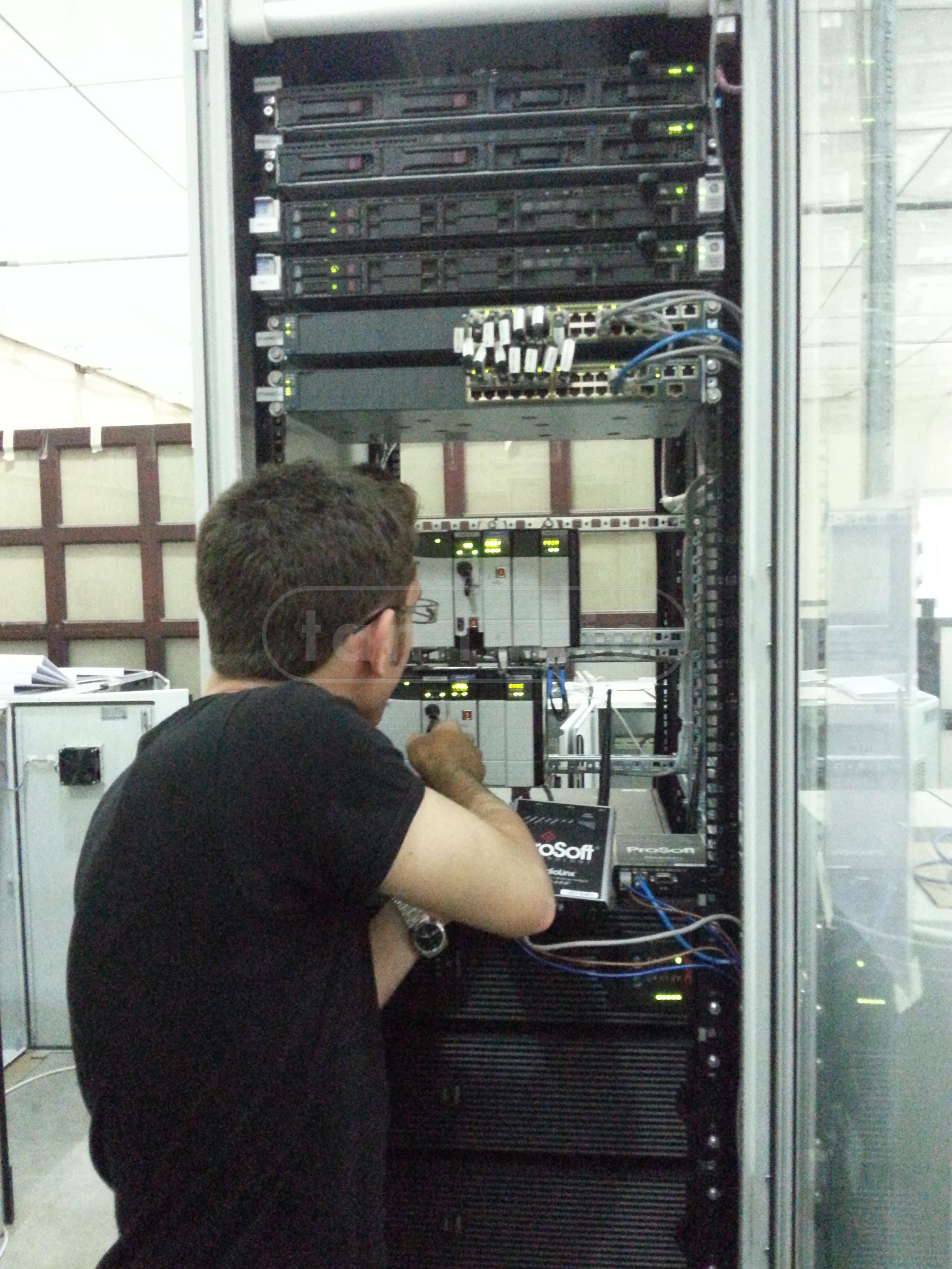
Img11: The MCC main panel, you can see me diving inside it!
The Project MCC was built from scratch, including the civil and mechanical work, for several reasons:
-
There was no building that met the minimum standards for a data center and an operation center. Building one allowed us to have control over all the details and design aspects, including the safety and security factors.
-
There was no building in the area designated for the MCC. The project area was divided into 4 zones, and the MCC should be somewhere in the middle of these 4 zones to allow proper wireless communications, and also for quicker access to the field if the operators needed to.
-
The project was very well funded and the timeline was sufficient to consider such a decision, either for the parts procurement or the installation itself. Plus, the MCC was not large and it was enough for the purpose it was built for.
The MCC had the following major components:
Hardware
- Two rack servers HP ProLiant DL360e/HP_ProLiant DL120 G7 with redundant configuration, off-site disaster recovery backup, and business continuity plan.
- Two main PLCs, LOGIX 5572 PROCESSOR with a redundancy module, 8 slots, ethernet module, among other peripherals.
- Managed L3 and unmanaged ethernet switches (Cisco catalyst).
- Rack mounted UPS, enough to power the whole panel and two screens for at least 5 hours.
- Main 70-inch LCD display, plus other display screens.
- HAM Radio unit for direct communication if needed to deploy an operator to the field.
- Other peripherals like alarm printers, etc.
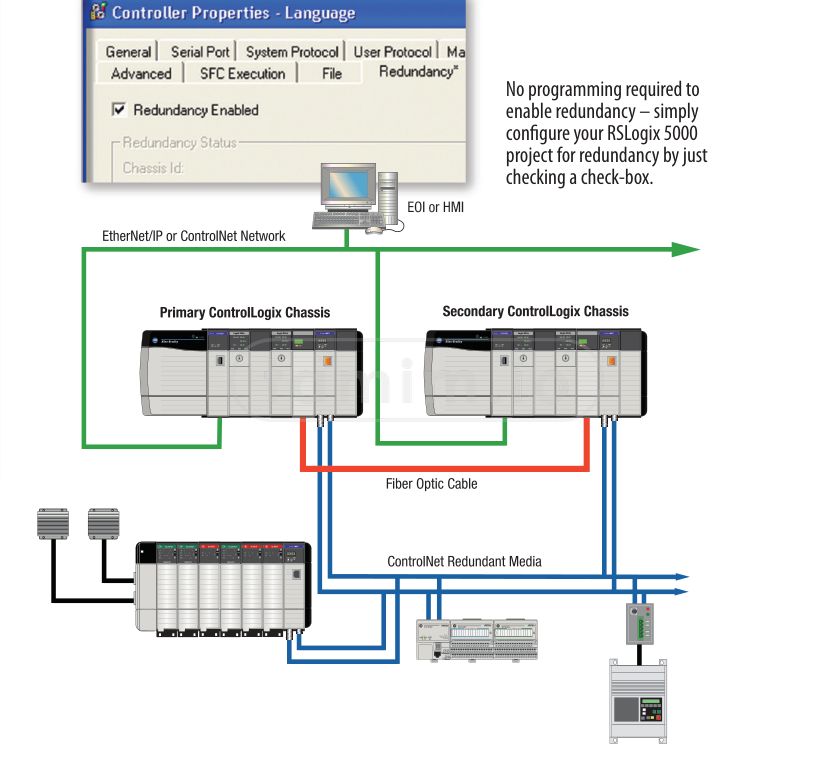
Img12: The main PLC redundant configuration
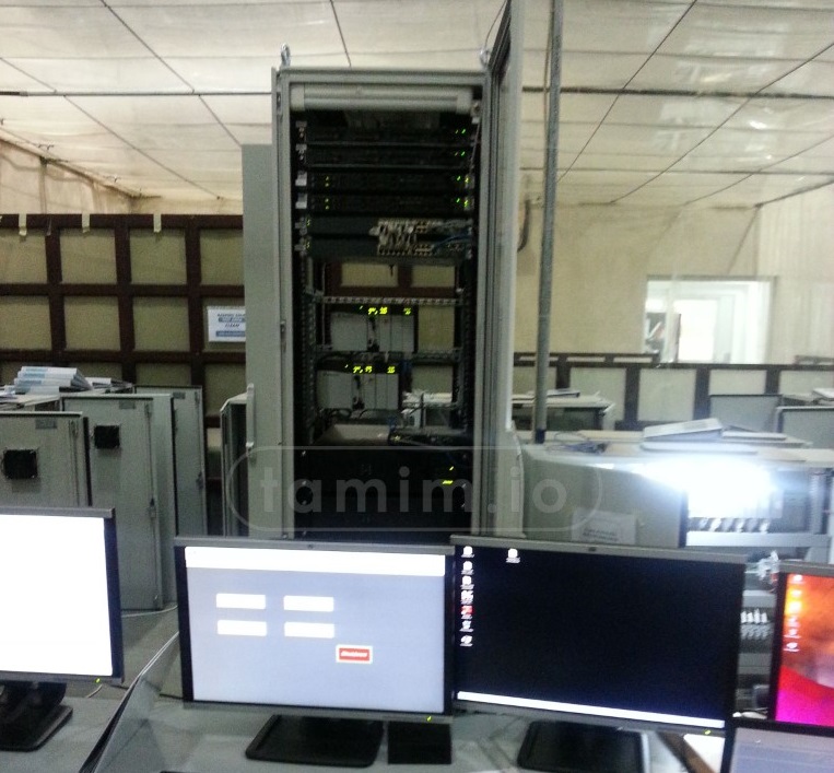
Img13: Not the most clear picture of the panel, but this was the main panel in the MCC, equipped with most of the hardware needed for the system
Software
- The main server OS was Windows Server 2012.
- Rockwell RS Logix 500, and RS Logix 5000, and Factory Talk Site Edition SE, RSLinx and Factory Talk Directory servers for the automation software.
- Database was MSSQL
- Other software for the wireless communication and network.
Some of the Rockwell Factory Talk Site Edition SE features per the manufacturer:
Scalable HMI solutions from single station to multi-client / multi-server systems
Continuous system visibility through FactoryTalk and redundancy-enabled HMI, Alarm, and Data Servers
Restricted access to control system assets and ability to meet the most stringent security requirements such as FDA 21 CFR Part 11
Among others.
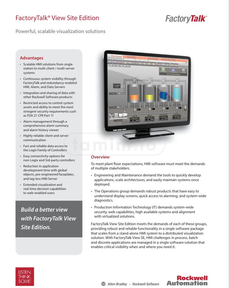
Img14: Rockwell Factory Talk Site Edition SE, the software that was used for the automation
Wireless Network
Img15: The master-repeaters-slaves locations in the project area and the four zones they serve.
Communication-wise, from the MCC to the field RTUs, was chosen to be wireless for obvious reasons given the size of the project area. Initially, the wireless communication I chose was in the range of ~900MHz, given it was cheaper and better for long distances (the higher the frequency the higher the noise), and there was no high throughput requirement like video feeds for example. However, the client lacked the license needed to broadcast in that band and within the allowed power range, and it was canceled. The second option I looked into was WiMAX2, the frequency for the industrial devices I found was around 3.5GHz, however, that also required a license the client said most likely they would not secure. The last option was to utilize the free frequencies that required no license, and for that, 5.8GHz with a fallback to 2.4GHz was used in the project.
The project was divided into four zones, the same zones applied to the communication architecture. The main 'Master' tower was at the MCC location, it communicated to four repeaters spread in the project areas, and each repeater broadcasted to the 'slave' station/RTUs.
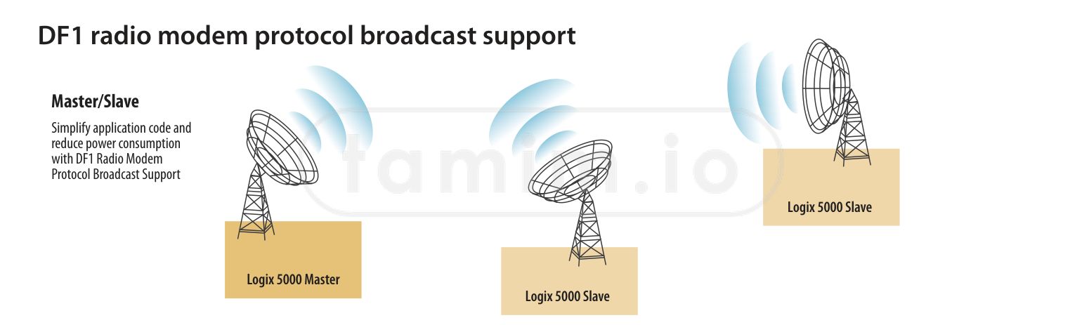
Img16: The wireless main topology
Directional (Parabolic) antennas were used between the master and repeater communication, repeaters were equipped with omnidirectional antennas, and the slave RTUs had the directional ones communicating with the repeaters. The parabolic antennas had a 50ohm impedance, 29dBi gain, max power 150 watts. Some of these four zones communication as follows:
The master and repeater towers had small panels attached to the tower to minimize any loss in the gain due to long coaxial cables between the device and the antenna. The slave RTUs, however, did not have that setup, as the impact was minimal and there was no need for a 24/7 uptime in that communication link, unlike the main ones, as one interruption would impact the whole zone.
Img17/18: Some of the zones in the wireless network
The wireless devices were from ProSoft, and they had more than enough features for the application in use, some of these features were as follows:
- 802.11n MIMO & Channel Bonding (up to 300 Mbps RF data rates), which was more than needed for the application in use.
- Built-in Serial Device Server, which was useful to monitor the device itself.
- OPC Diagnostic Server that enabled diagnostic tags to be read in SCADA and historian software.
- Operating Temperature: -40°C to +75°C (-40°F to +167°F), Humidity: Up to 100% RH, with no condensation
- External Power PoE Injector Those were some of the main features that were used, the rest of the list below:
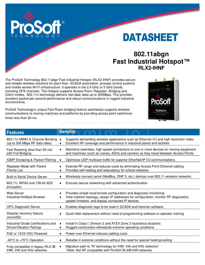
Img19: Prosoft Industrial Hotspot specs, the device that was used for the communications in the project
Network Architecture
The network architecture, on the other hand, was very similar to the diagram below. The network had mixed protocols, from ethernet, to profinet, to modbus, among others.
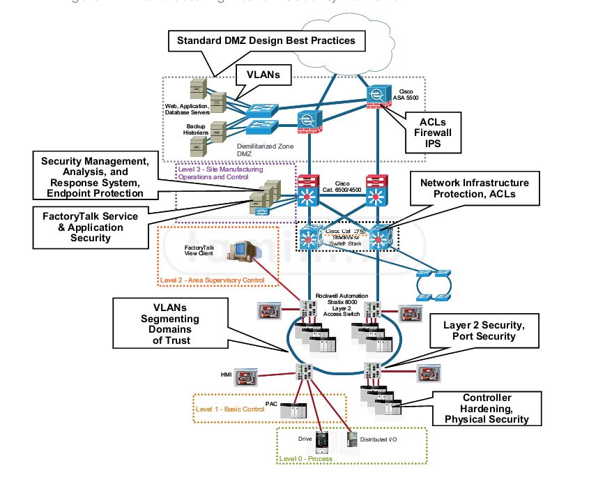
Img20: The network architecture of the SCADA system
The network was isolated, VLANs were in place, and the granular access was provided, from root access to administration, to the engineer access, operator, and finally the viewer access, which was the only access that could possibly be accessed through the internal company network, for security reasons. The cybersecurity in this project was extended for a follow-up project, where it was hardened and audited against the standards such as NIST, ISO27001, and SANS, more about it in here Industrial Automation Systems Cybersecurity Pentest & Audit
Challenges
The challenges of this project mainly fell into one of these categories:
-
Logistics and procurement: the project faced several challenges in that regard, the major one was the wireless equipment, due to the amount of devices ordered, it created some delays at the customs.
-
Design related challenges: the project had many of these, as the work in the design phase went through several iterations and changes, like the one mentioned above for the wireless licensing.
-
Installation related challenges: as the transformation to automation impacted real customers, there were a lot of challenges on the schedules of the installations, sometimes the team had to work in the night time when some of these facilities were shut down, sometimes working continuously over shifts as the working window provided was short and if the work was not done, the team had to wait for the next week.
Conclusion
This project was a successful example of how automation and wireless communication can improve the efficiency and reliability of a large-scale operation. The project involved designing, developing, procuring, configuring, and installing a turnkey SCADA system that replaced the manual operations with fully autonomous and monitored systems. The project also included a complete and comprehensive infrastructure overhaul, including civil and construction work, wireless network, and a data center room. The project faced several challenges in logistics, procurement, design, and installation, but they were overcome with careful planning and coordination. The project delivered a state-of-the-art automation system that enabled full control, alarm, data collection, reporting, and remote monitoring of the system components. The project also paved the way for future projects in cybersecurity, solar power, and WiMAX communication. The project was a rewarding experience for me and my team, as we learned a lot from the various fields and technologies involved.
Note: The comment section is powered by Cactus/Matrix. If you use the official Matrix server, you are good to go. However, if you use your personal Matrix server, make sure to log in with the first button and use your own client. This is because my CSP only allows Cactus/Matrix domains to connect from this site, and most likely, your profile picture will be broken!
Ladder language
WiMax Frequencies